BACKGROUND
The energy industry is under constant pressure in all production environments In the face of rising costs and increased operating demands, exploration & production (E&P) companies are looking to maximize production – while ensuring safe operations and avoiding environmental impact
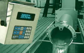
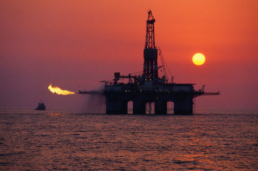
During the exploration and drilling stages at oil and gas fields, accurate and dependable flow metering equipment is essential to ensure production is optimized Produced water applications, in particular, challenge oilfield operators The costs associated with these processes can adversely affect the economics of the producing wells, thereby discouraging further development and leaving substantial reserves unrecoverable (See Fig 1)
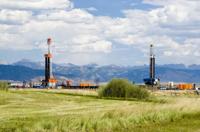
Figure 1: During the exploration and drilling stages at oil and gas fields, accurate and dependable flow metering equipment is essential to ensure production is optimised.
This whitepaper describes how instrumentation manufacturers have responded to the needs of the upstream sector by offering proven metering techniques to meet demanding flow measurement requirements
INTRODUCTION
In the oil and gas industry, recent technological developments are changing upstream production dramatically and opening up reserves to economically viable extraction Unequivocally, this new development will have repercussions for the environment and the development of renewable energy and a sustainable energy economy
There is an ongoing global shift to unconventional resources such as shale and oil sands Many of the extraction techniques associated with these newer plays – such as hydraulic fracturing – are very water-intensive (See Fig 2)
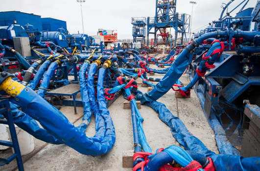
Figure 2: Many of the extraction techniques associated with shale oil and gas plays are very water intensive.
Producing petroleum products out of the ground generates large volumes of water with undesirable qualities Produced water contains soluble and insoluble organic compounds, dissolved solids, production chemicals (corrosion inhibitors, surfactants, etc ) and solid particles
For petroleum companies, salt water produced during production operations constitutes a critical waste stream affecting their bottom line The disposal cost, covering transportation, capital requirements and infrastructure maintenance, may be as much as $10 00 per barrel A typical production field can produce tens of thousands of barrels of salt water each day
GROWING ENVIRONMENTAL CONCERNS
With an increased focus on corporate responsibility and sustainability, the proper handling and disposal of waste streams is critical to all oil- and gas-related businesses Operators must ensure regulatory compliance while protecting assets, personnel and the environment
Prior to environmental regulations in the 1970s, produced salt water was disposed of using the most economical method available – often times intentionally discharging the water on the ground These past practices and current accidental releases of produced water are national issues that concern managers of Native American, federal and state lands, as well as oil and gas producers, mineral rights and lease owners, state and federal regulators, and landowners
Tight gas, shale gas, oil shale, and liquids-rich, low-permeability plays are now frequently economically viable, and they are being produced in higher volumes than ever before Along with the higher volumes of oil and gas are increased amounts of produced salt water
CHALLENGES FOR WELL OPERATORS
The flow of liquids and gases must be measured during every phase of oil and gas exploration, production and transportation This includes production well testing, enhanced oil recovery, fracking and separation to recover and prepare crude oil and produce water These applications demand the highest flow meter accuracy and reliability, as well as long-term stability and a low cost-of-ownership
Today, E&P companies have an urgent need to meet their water management challenges One of these challenges, in particular, is the fact that produced water streams must often be treated prior to disposal or reuse The
capital and operating costs associated with most treatment systems can be very high The need for economical management of produced water is critical
After the drilling & completion phases, the production phase utilizes three-phase separators to separate produced water from oil and gas Pump trucks visit well sites on a frequent basis to collect the water and haul it away to an offloading Salt Water Disposal (SWD) facility In certain areas, this is a very costly practice
The disposal of produced salt water, as well as other defined oil and gas wastes, is controlled by each state’s regulatory agency The most common disposal method is to inject the produced water and associated wastes into suitable, naturally occurring formations
Increasingly, oil and gas firms are seeking to minimize the need to inject produced water at disposal sites, reduce water trucking costs – and at the same time – increase production
PROVEN METERING TECHNIQUES FOR WATER BASED MEDIA
There is no question that flow measurement is a crucial aspect of numerous upstream operations – especially those around produced water With countless measuring instruments currently available, making an optimal meter choice can be a daunting task for operating companies Each type of flow meter used to measure oil & gas flow has its own advantages and disadvantages
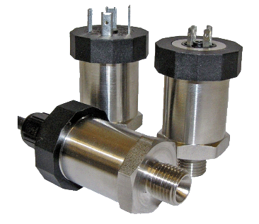
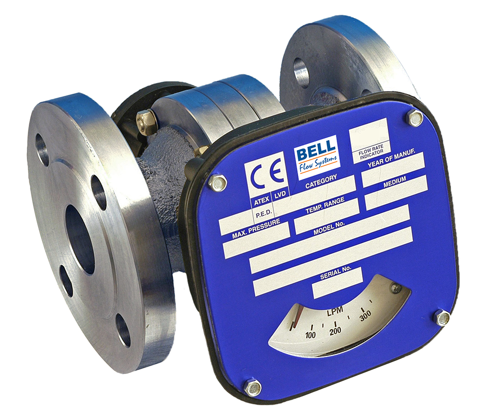
Although electromagnetic flow meters have specific, limited uses in the oil and gas industry (since hydrocarbons are non-conductive), they are a reliable, cost-effective solution for chemicals, slurries and water/produced water, providing highly accurate volumetric flow measurements Magnetic meters are gaining usage in liquid separators, fracturing water, drilling mud and SWD applications
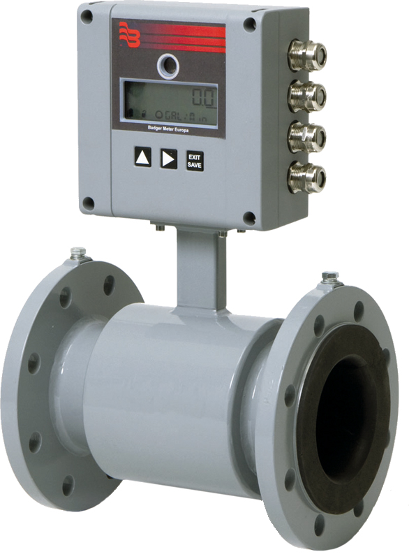
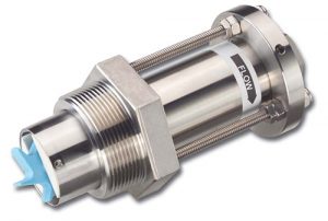
For example, produced water from well operation is highly conductive, and as such, an electromagnetic meter is one of the most popular approaches for measuring its flow Due to sediment and particulates in produced water,
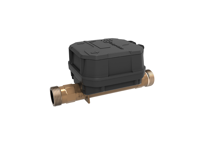
a flow line may need to be pigged, making the electromagnetic meter an ideal choice Because these meters have no moving parts in the line, they can be pigged without shutting down the process to remove and reinstall the unit (See Fig 3)
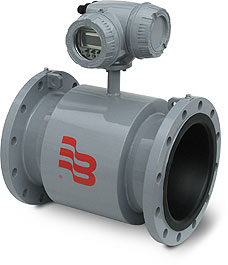
Figure 3: Produced water from well operation is highly conductive, and an electromagnetic meter is one of the most popular approaches for measuring its flow.
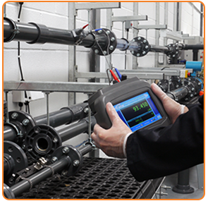
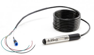
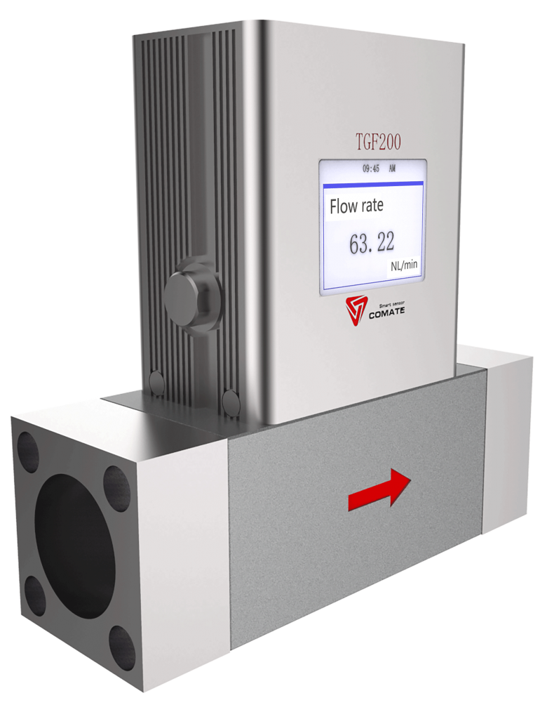
The two main ultrasonic flow meter technologies are transit time and Doppler Transit-time flow meters are based on the time difference between upstream and downstream sound propagation intervals Doppler flow meters are based on the Doppler Effect The most commonly used ultrasonic device is the transit-time, single-path meter due to its proven accuracy, flexibility, and low cost
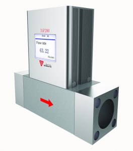
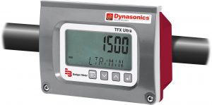
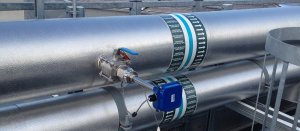
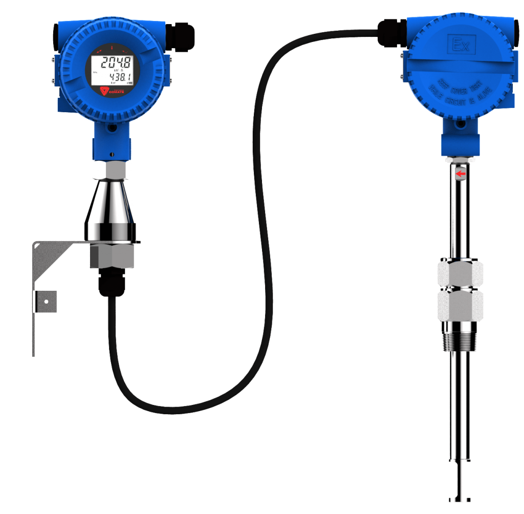
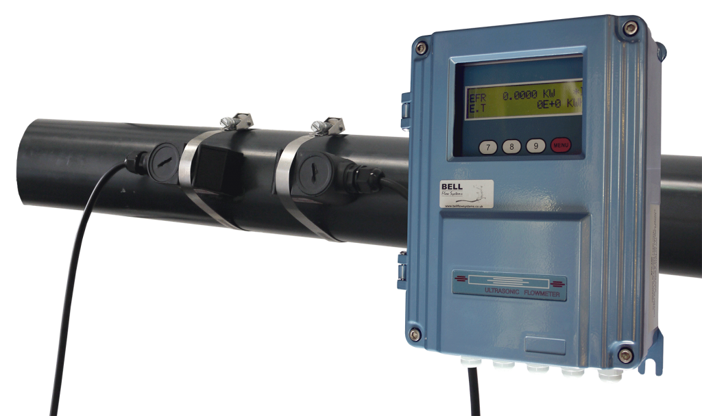
The demanding measurement requirements and challenging environmental areas found in the upstream sector can often lead to the selection of ultrasonic flow meters The fluid used in oil extraction and production is frequently pumped at high pressure and flow velocity, making the use on an invasive flow meter highly
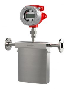
challenging Many companies are also choosing ultrasonic meters because they can handle impurities in the flow better than most other designs (See Fig 4)
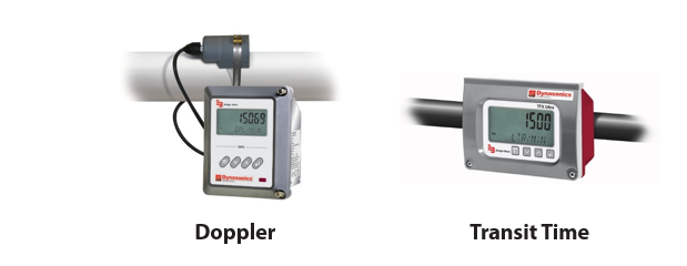
Figure 4: The demanding measurement requirements and challenging environmental areas found in the upstream sector can often lead to the selection of ultrasonic flow meters.
Wastewater Evaporators
Recent innovations in evaporation technology provide operating companies with an efficient, economical and environmentally responsible way to minimize wastewater transportation and disposal Key to this solution is accurate measurement of the evaporation process provided by electromagnetic flow meters
During the operation of a wastewater evaporator, the volume of high total dissolved solids (TDS) water entering the system is metered, followed by a measurement of the amount of salt crystals or concentrated water exiting the unit The delta of these two measurements is used to calculate the evaporation total, which is the basis for a per barrel service charge billed by the evaporator system provider to the oilfield operator
When used as part of an evaporation system, the electromagnetic flow measurement technique eliminates the need for moving parts, which can lead to performance and maintenance issues The meters measure virtually any conductive fluid or slurry, and are known for low pressure drop, high accuracy, extended turndown and excellent repeatability
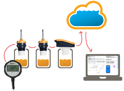
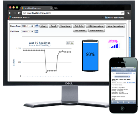
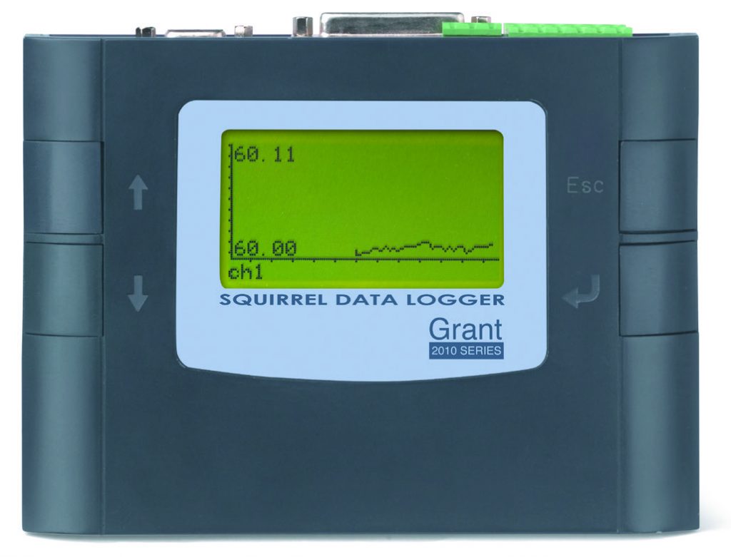
Accurate flow data helps enable secure remote operation of an evaporator system – simplifying site personnel training and reducing overhead costs Additionally, improved reliability, increased robustness and reduced maintenance requirements can be achieved (See Fig 5)
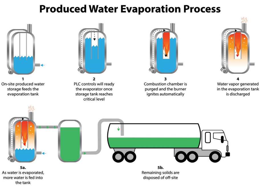
Figure 5: Accurate flow data from electromagnetic flow meters can help enable secure remote operation of a produced water evaporator system.
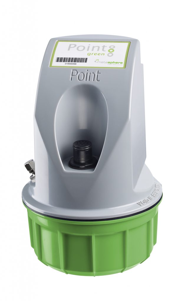
In the future, cloud-based software solutions paired with wireless electromagnetic flow meters will enable unmanned monitoring of produced water consumption, storage and transportation at remote oilfield locations These systems will utilize endpoints to capture interval meter reading data through cellular or fixed network communication technologies They will employ data from the wireless mag meters to provide operators with readings of flow rates and hourly/daily/monthly totals, tank levels and other key parameters without visiting the well site Production decisions can then be made at a central operations centre to help optimize large producing fields
Hydraulic Fracturing
Hydraulic fracturing is the use of fluid and material to create or restore small fractures in a formation in order to stimulate production from new and existing oil and gas wells Fracturing creates paths that increase the rate at which fluids can be produced from the reservoir formations, in some cases by many hundreds of percent
Hydraulic fracturing is another common oilfield application for electromagnetic flow meter technology During this process, a mixture of abrasive sand, gel and water is pumped at high pressure into underground rock layers
where oil or gas is trapped Gelling agents are used for lubrication to increase fluid viscosity and make it better able to carry sand This is a key step in holding fractures open Additional chemical injection is used to reduce friction, attack microbes and minimize equipment corrosion
Electromagnetic flow meters are the perfect fit for skid installation, require upstream/downstream straight pipe runs, and provide high measurement accuracy Compared with traditional mechanical meters, electromagnetic meters reduce or even eliminate expensive service, replacement part costs, and downtime
By employing electromagnetic flow meters, operating companies can maintain precise control of the fracturing fluid and the blending of additives This application wears out many other flow meter technologies and can result in an unstable flow signal, making the measurement unusable Once the fracturing process is complete, production can begin
Drilling Mud
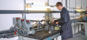
During drilling and wellhead installation, precise control of the flow rate of drilling mud going down the borehole to cool the drill bit is a critical step in preparing the well The drilling mud is typically a mixture of water, sand and
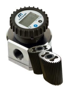
a range of chemicals The flow meter used in this application must be able to withstand abrasive materials as well as harsh environmental conditions such as moisture, varying ambient temperature ranges, and vibration in the drilling rig (See Fig 6)
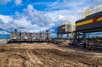
Figure 6: Flow meters used in drilling mud applications must be able to withstand abrasive materials as well as harsh environmental conditions.
The use of electromagnetic flow meters to measure drilling mud can enable oilfield operators meet rigorous production requirements, reduce risk and avoid unnecessary downtime The meters utilize long-lasting sensor lining materials to ensure resistance to chemical corrosion and abrasion, resulting in extended service life
Unlike many other flow instruments, they have no rotating parts inserted in the pipe This can help do away with premature wear, frequent maintenance and associated service costs
At the same time, non-intrusive ultrasonic flow meters perform efficient measurement of mud flow system return lines when the drilling mud contains beads, which are good reflectors for Doppler ultrasound metering technology
Phase Separators
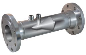
Phase separators reside on onshore well pads and offshore platforms and can be horizontal or vertical They’re used in upstream oil and gas applications for periodic well testing (as a test separator) or continuous production measurement (as a production separator), and can function in either two-phase or three-phase depending on operator strategy (See Fig 7)
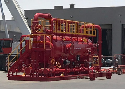
Figure 7: Oil three phase separators are used to separate the oil from the gas and water.
The separator is primarily intended to separate the oil from the gas and water On a three-phase separator, all the phases have to be accurately measured and monitored Electromagnetic flow meters are a common choice for water measurement process due to their straightforward design with no moving parts and no path obstructions The meters provide accurate flow readings, which tell operators how their wells are performing and how much oil, water, and gas they’re producing These measurements also assist with fine-tuning recovery operations to maximize retrieval of hydrocarbons
Salt Water Disposal
The process of oil and gas production creates “salt water,” which is considered a hazardous waste because of its high salt content, hydrocarbons, and industrial compounds Companies can recycle the water, injecting it back into working reservoirs for reuse in gathering any remaining oil or gas, or they can discard it at a salt water well disposal site
Ultrasonic flow metering has gained popularity for salt water disposal applications Installation of the meters takes place without interrupting the production and without cutting into the pipe The transducers are simply clamped onto the pipe and do not cause any pressure loss Since they do not come in contact with the medium, they are not subject to wear And, with its sophisticated ultrasonic transducers and superior signal processing capabilities, the measurement system is highly accurate and reliable
Electromagnetic flow meters also play a role in salt water disposal They can be used to reliably measure abrasive discharge fluid pumped to and from wells, and are robust enough to withstand operational vibration on truck- mounted, process water blending units
BENEFITS TO E&P COMPANIES
Whether it’s improving accuracy, decreasing system maintenance or meeting the demands of challenging liquid and gas conditions, modern flow meter technology delivers the performance critical oil and gas applications require
There are numerous benefits to using electromagnetic flow meters to perform fluid flow measurements in E&P operations They are generally non-invasive and have no moving parts, reducing the risk of breakdowns and the frequency of repairs Increased activity in oil and gas production and exploration will continue to put ultrasonic flow meters in the measurement spotlight These meters are simple and inexpensive to install
CONCLUSION
The oil and gas industry deals with a host of troublesome applications, including produced water evaporation, hydraulic fracturing fluids, drilling mud, three-phase separators and salt water disposal Such applications can be difficult for many flow measurement instruments to handle
Sticking to the old adage of “if it’s not broke don’t fix it” – and not utilizing the best available technologies – could cost petroleum producers and other support companies millions of dollars For many oilfield operators, advanced electromagnetic and ultrasonic flow meters are the instruments of choice when considering cost, accuracy and the service life of installed equipment
ABOUT BADGER METER
Badger Meter is an innovator in flow measurement and control products and is represented in the UK by Bell Flow Systems Ltd. The company’s products measure water, oil, chemicals, and other fluids, and are known for accuracy, long-lasting durability and for providing valuable and timely measurement data For more information, visit www.bellflowsystems.co.uk or www.badgermeter.com
Trademarks appearing in this document are the property of their respective entities. Due to continuous research, product improvements and enhancements, Badger Meter reserves the right to change product or system specifications without notice, except to the extent an outstanding contractual obligation exists. © 2018 Badger Meter, Inc. All rights reserved.