

Turbine Flow Meter Guide
About Turbine Flow Meters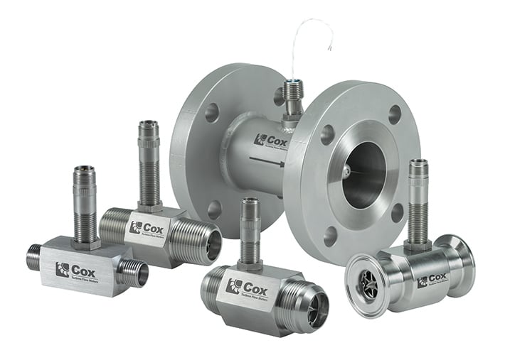
Turbine meters measure flow using the mechanical energy of the fluid or gas to rotate a turbine rotor within the flow stream inside the meter. The rotations are measured and calculated to provide a proportional measurement relative to flow rate. The Principle is well proven and the application suitability list is very large.
How do Turbine Flow Meters work ?
The flowing fluid/gas engages the turbines' rotor causing it to rotate at an angular velocity proportional to the fluid flow rate. The angular velocity of the spinning rotor results in the generation of an electrical signal (AC sine wave type typically) in the pickup which is located on the body of the flow turbine but is not usually wetted. The summation of the pulsing electrical signal is related directly to total flow, based on the calibration data created for that specific flow turbine. The frequency of the signal relates directly to flow rate. The rotor (or dual rotors) is the only moving part of the flow meter.
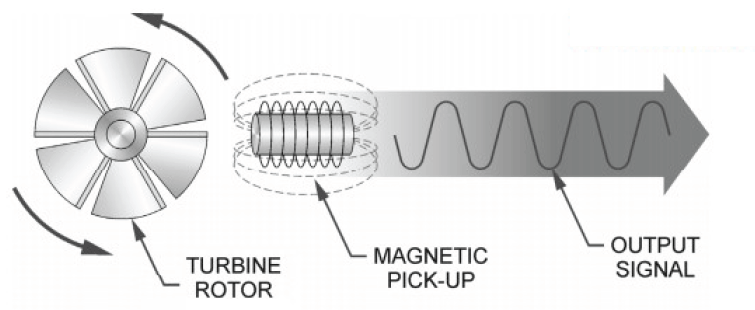
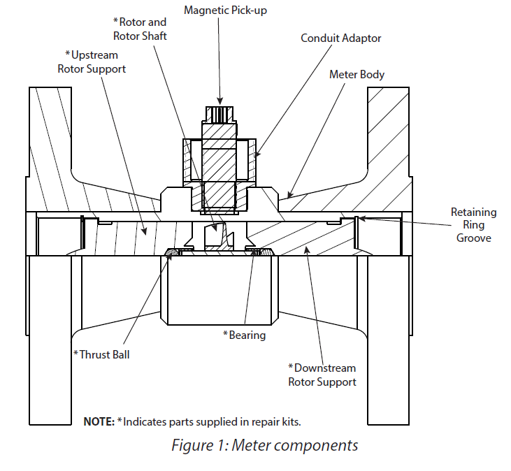
Figure 1: Typical Turbine Flow Meter Construction
The Turbine flow meter (axial flow turbine) was invented by Reinhard Woltman in 1790 and is an accurate and reliable flow meter for many liquids and gases. It consists of a flow tube with end connections and a magnetic multi bladed free spinning rotor/impeller mounted inside, in line with the flow. The rotor is supported by a shaft that rests on internally mounted struts or supports. The Supports in Turbine Flow Meters are designed to also act as flow straighteners, stabilizing the flow and minimizing the negative effects of turbulence and swirl. The supports also house the bearings, allowing for the measured media to lubricate the bushes (Sealed grease bearings are often used for gas) – prolonging the flow meters life span. The Supports are usually held in position by locking rings or circlips at each end.
The rotor sits on a shaft, which in turn is suspended in the flow by the two supports. As the media flows, a force is applied on the rotor "wings". The angle and shape of the wings or blades transform the horizontal force to a perpendicular force, creating rotation. Therefore, the rotation of the rotor is proportional to the applied force of the flow. Because of this, the rotor will immediately rotate as soon as the media induces a forward force. As the rotor cannot turn through the media on its own, it will stop as soon as the momentum of the media stops. This ensures an extremely fast response time, making the Turbine Flow Meter suitable for low to medium speed batching applications.
A pick-up sensor is mounted above the rotor, usually recessed into the meter body, but still behind a "window" of material, thus allowing for high pressure models to be designed. When the magnetic blades pass by the inductive pickup sensor, a signal is generated for each passing blade. This provides a pulsed signal proportional to the speed of the rotor and represents pulses per volumetric unit and as such the flow rate too. (Meter calibration and indeed multiple points of calibration to for a linearisation table ensure true meter accuracy)
Advantages:
♦ Measures thin and also viscous liquids (Special models for high viscosity)
♦ Accurate and repeatable measurement at a relatively low price
♦ Super high-accuracy dual rotor models available
♦ High Pressure models available
♦ Gas flow models are widely used for custody transfer applications
♦ Good Turndown range
♦ Wide choice of materials
♦ Wide range of sizes & fittings available
♦ Hygienic models available with Sanitary approvals
♦ Suitable for high temperature applications
♦ Low pressure drop across meter body
♦ Weights & Measures approved models available
♦ Suitable for hazardous areas
♦ Low cost of ownership / proven design
♦ Easy to install
♦ Simple and proven design facilitates in-field repair
♦ Integrated or remote display, even battery power models are possible
Disadvantages:
♦ Pulsating flows are not tolerated and will affect the readings
♦ Affected by flow profile (flow conditioning required eg, straight pipe lengths or diffusers)
♦ Not suitable for liquids with entrained air as false readings will result
♦ Not suitable for liquids susceptible to shearing
♦ Not suitable for liquids with solid particles or contamination (requires filtering)
♦ Very Heavy at larger sizes
♦ Viscous fluids are not suitable for measurement
♦ Requires constant backpressure to prevent cavitation
♦ Sensitive to changes in fluid viscosity
Typical applications:
♦ Turbine flow meters are often suitable for measuring bulk fuels and light oils. Other industries that use these flowmeters include aerospace, water, chemical, pharmaceutical and food and beverage.
♦ In addition to metering chemicals, water, and fuel, they are used in oil drilling operations or for metering cryogenic gases.
♦ Sanitary flow turbines with 3A approval are widely used to measure wine, spirits and beer
| View our range of Turbine Flow Meters |