

Categories
Product Selector
News
- Apr 9, 2024 Versatile D-Series Flow Displays D-Series DIN Standard Panel mount Flow Measurement displays... Read more
- Feb 12, 2024 Coriolis Mass Flow Meters - ATEX Certified CG range of high performance ATEX approved Coriolis flow meters for Liquids and Gases. ... Read more
- Jan 2, 2024 TBQSe Digital Gas Flow Meters with built-in EVC These turbine flow meters are ideal for commercial and industrial applications for measuring natural gas in pipe sizes from DN25 up to DN150.... Read more
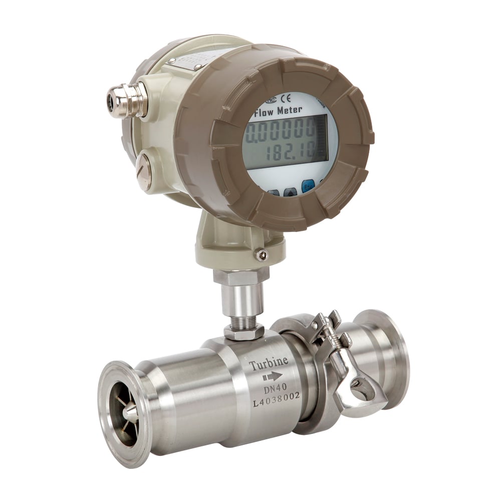
BLFT Stainless Steel Turbine Flow Meters
BLFT Liquid Flow Turbine Meters are a lower cost alternative to existing products available in the market.
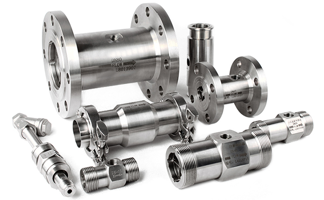
BLFT Liquid Flow Turbine Meters can be specified in a wide variety of sizes and connection options. This range has been independently tested to UKAS national standards to guarantee performance. A choice of signal outputs and display options makes this range extremely versatile.
This highly accurate Flow Turbine style meter is constructed from either 304 or 316 grade stainless steel and is ideal for the measurement of various low to medium viscosity liquids in a range of different applications. This model is supplied with a square wave pulse output or low voltage coil pulsed signal as standard, with a wide choice of digital flow displays and batch controller’s available. The standard low cost digital display is powered by a lithium battery with a long battery life of 4 years, providing a choice of 4-20mA signal, pulsed output and programmable alarms.

BLFT turbine flow meters are ideally suited for measuring low to medium viscosity liquids and can even handle aggressive fluids or liquids that require hazardous area ATEX approval. Typical applications include measuring bulk fuels, solvents and light oils as well as chemicals, additives and water. Sanitary flow turbines are widely used in hygienic food and beverage industries to measure wine, spirits and beer as well as fruit juices, milk and others.
Sizes available range from DN4 to DN200 and models can be specified with a choice of maximum temperature, pressure and even face to face dimensions. BLFT bearings and shaft material is Tungsten carbide, while rotor material is CD4Mcu. Accuracy can be specified at +/- 0.5% or 1% of measured value with repeatability stated at +/-0.2%. This range can be supplied with a wide selection of basic or advanced flow computers offering temperature compensation and flow curve linearization.

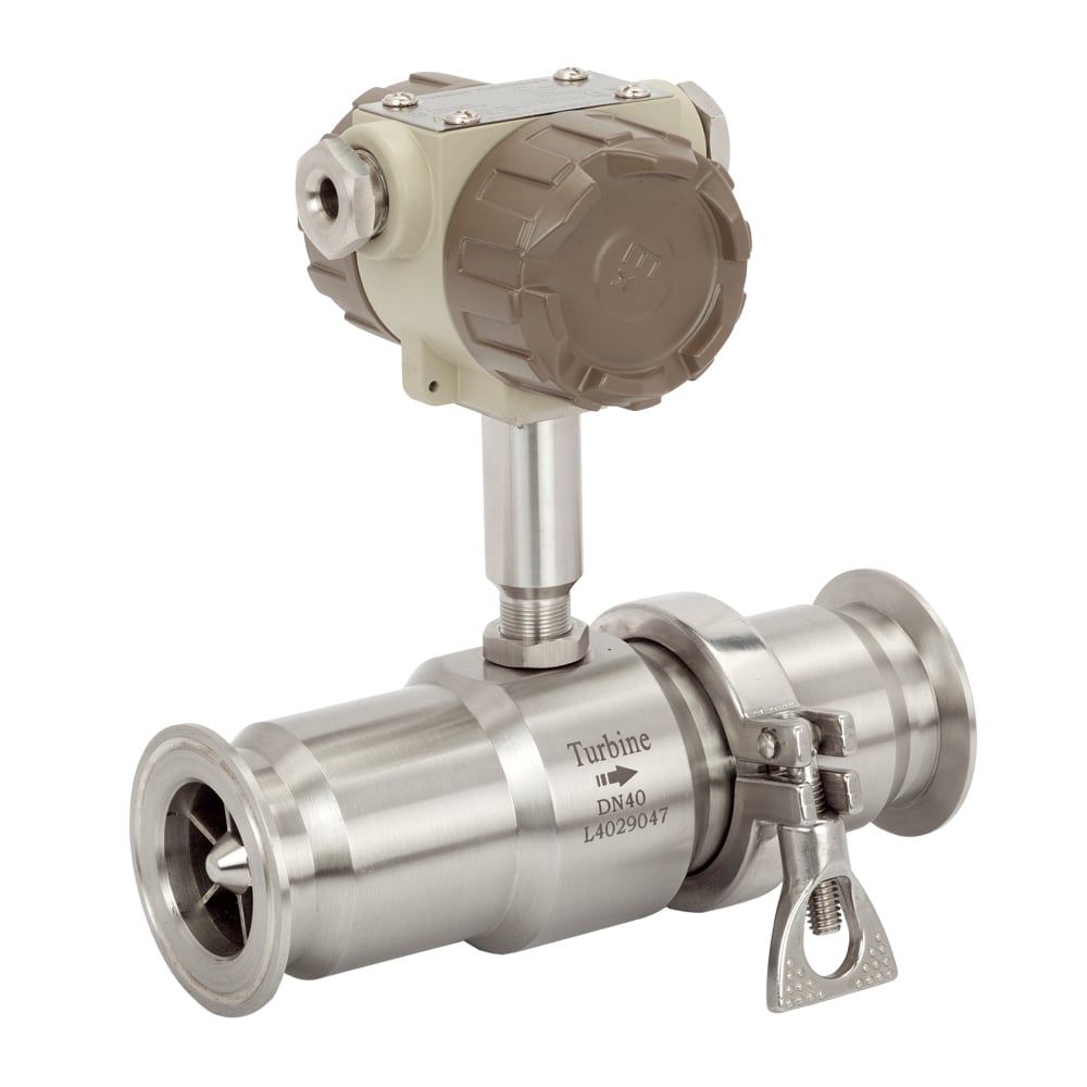
Turbine meters measure flow using the mechanical energy of the fluid to rotate a turbine rotor within the flow stream inside the meter. The rotations are measured and calculated to provide a proportional measurement relative to flow rate. The Principle is well proven and the application suitability list is very large. The flowing fluid engages the turbines' rotor causing it to rotate at an angular velocity proportional to the fluid flow rate.
The angular velocity of the spinning rotor results in the generation of an electrical signal (AC sine wave type typically) in the pickup which is located on the body of the flow turbine but is not wetted. The summation of the pulsing electrical signal is related directly to total flow, based on the calibration data created for that specific flow turbine. The frequency of the signal relates directly to flow rate. The rotor is the only moving part of the flow meter.
Click for info and prices >>> Turbine Flow Meters


